hello:
does anyone knows what should i do if i got the message which says that: " reading GiD mesh ’ XXX’ in this line: 471:: 18712 not in [ 1, 340] node 18712 out of range.
Point number out of range?: 19 not in [ 1, 18] Reading mesh."?
It seems that the file you are reading is wrong or doesn’t has the expected syntax.
e.g. some element points to the node id=18712 but this node has not been previously defined.
Have a look to the file content with some text editor (in case that it is ASCII) to try to identify the error.
How are you reading the file in GiD? (e.g. Files->Import->GiD mesh… in preprocess, Files->Open in postprocess,…)
How has been created the file?
If you are unable to solve your problem upload the file to this forum.
hi escolano:
thanks a lot for helping me.
i’ve tried the way you suggest while it’s not working.
i have the file as in .txt format which i want it to be uploaded, while it seems that the .txt file is not allowed to be uploaded.
Am i only allowed to attach pictures to this message?
Hi escolano:
The txt file is attached to this message, and i really appreciate if you can help me have a look of it and point out the whats wrong with my mesh.
Thank you.
Hi escolano:
that is exactly the problem is, and after correct that point, the mash can be imported into the GiD.
While the imported mesh is looking pretty strange as shown in the picture attached, can you have a look to see if you think it’s in a wrong format?
Hi escolano:
the original mesh i have are triangulated surface meshes, and i used the command that you told me (Mescape Meshing MeshFromBoundary) in the GiD which generated my mesh into linear 4 node tetrahedral meshes.
then i used a matlab code converted them into quadratic tet.
Is the wrong order of element’s node happens during using the command?
Hi escolano:
Really appreciate your answers to my concerns.
I know how does the 10 node tet’s element should be arranged while i don’t know what’s the problem my Matlab code exactly, with keeping the first four nodes and obtained as averages of pairs of the first four nodes for the rest six nodes.
This question might be the last one on my simulation, and i sincerely appreciate that if you can help me on tackle it, or if you know any other code or program can convert my 4 node tet into the right order of 10 node tet.
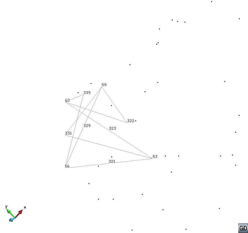
in this image you could see that the 5th local node must be the one located between the 1st and 2nd local nodes (edge 1-2)!!
seeing the ‘garbage image’ you could identify that the ‘midnode’ between the nodes 59 and 56 must be 329, then this 5th node is ok,
the 6th node must be in the edge 2-3 (your global nodes 56-62), by the image this node must be the 331, not the 339 like your wrong file!!
And so one… this is the good order of your element 1
Elements
1 59 56 62 53 329 331 339 322 321 323
…
End Elements
And the same permutation of columns for the rest of elements (to be done in your matlab code)
Hi escolano:
I’ve made the change in my code for reordering the node of element as you said.
That is by change the ordering as:1, 2, 3, 4, (1+2)/2, (1+3)/2, (1+4)/2, (2+3)/2, (2+4)/2, (3+4)/2
to :1, 2, 3, 4, (1+2)/2, u/2[/u], u/2[/u], u/2[/u], (2+4)/2, (3+4)/2 to fit the GiD acquirement.
While the output is quite strange as shown in the attached file.
The other files are also attatached.
Thank you if you can have a look and provide some help on this.
must be like your previous example:
MESH dimension 3 ElemType Tetrahedra Nnode 10
Coordinates
1 17.905779 -102.379013 5.453694
2 17.688734 -94.298431 0.82639
… 0001r-100b_fixed.zip (8.62 KB)
and about your reorder of element’s nodes
what do you mean for example with (1+2)/2 ???, this is a real number=3/2=1.5, not an integer !!!
Hi escolano:
Thank you soooooo much and it works now~~~
Just one more question, which after reading the tutorials in the GiD about “point”, i still don’t know precisely about how to move one mesh to a desired point (e.g. a random point my mouse pointed)
i am intended to use the utilities → move, what i don’t understand about it is the “num (x,y,z)” in the “first point” and the “second point”, are these two points intended to be combined as a vector?
Utilties->Move.. is another tool, similar to Utilities->Copy…
It try to apply a transformation that could be a translation, rotation, mirror, scale,…
depending on the transformation two or more points (its coordinates) are required to be defined.
e.g. A translation is defined by the relative increment from ‘First point’ to ‘Second point’
a rotation in 3D is define by tho points on the rotation axis
a mirror in 3D is defined by three points on the plane of the mirror.
…
The move tool is not able to ‘deformate’ the geometry or mesh
and if do you select a part of a model instead of a move could be necessary to create a copy of some shared entity
You must follow the basic tutorials that explain the use of this tool
Mesh->Edit mesh->Move node
or Geometry->Edit->Move point
do other things, it try to deformate somehow the connected curves and surfaces.
Dear escolano:
I really appreciate your help without which i can’t correctly convert my meshes into a right format that could be read by the GiD.
I am currently using the MayaVi as a visualizer for the output of my GiD simulation, while there seems to be some problem as it requires me to move my meshes into a specific regime, or these meshes will either be presented as a flat surface or be cut by a invisible plane. Any idea about this?
Also, i’m still confused with the utility->move option, in which i don’t know quite clear how should i pick the “first point” and the “second point” if i want to move the mesh as a element to a desired point.
If you have never used MayaVi, then can you tell me how to generate a good postprocess result, like those in the attached file?