Hello every one,
I am a new user for GID and, now studying the Tutorial.
I have a problem during studying the Tutorial.
I dont know why it happen even I follow every step in the Tutorial.
The geometry view is as same as shown in the Tutorial, but the mesh is wrong.
Could anyone give me a suggestion for this problem?
And one more question, does GID has an undo function?
Try re-opening the file, How look the mesh then?
(without re-mesh, in some case seems that the mesh really is internally ok, but its representation inside the graphic card become wrong)
Check also that do you have only a volume, maybe there are more than one with the same surfaces as boundary
Thank you very much for your suggestion.
It seems to be o.k. after I re-opened the program.
May i ask you one more question?
Now, i am leaning how to use GID
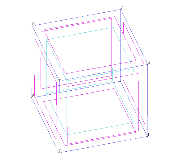
I try to follow the instruction, but sometimes the error was found after I generated mesh. (please see the attach file)
In my opinion, the program should automatically generate the uniformly and symmetry mesh. (my opinion may be wrong)
So I would like to ask you that in case I did some thing wrong during drawing the model, which cause the wrong mesh generation.
What should I do? can I correct the model without re-drawing.
The problem of show just after mesh a wrong mesh, like your initial picture (where seems that some nodes are in a wrong location)
only happen in some rare case and never happened in our machines.
It is a graphic problem, the mesh and the node coordinates are ok, saving and opening again the mesh is refreshed ok in screen also.
It seems a problem with a combination of graphic card+driver+GiD version+Open GL options used
I suspect that is related with Vertex buffer objects and Vertex array methods, where coordinates are copied to the graphic card memory to accelerate drawings,
try changing Utilities->Preferences… Graphical->System->Method: Display lists or Immediate
and maybe is not happening in latest GiD versions (you can try last the 13.1.11d developer version)
What is your operating system? Windows, Linux? Which version?
Hello, Thank you very much for your suggestion.
I had tried to change Graphical System, but it did not work.
Now, I installed this program in 2 computors, one is Windows 10 (laptop lenovo thinkpad x250), and another is Windows 7 (PC).
Both pc show the same results for this model (the previous attached image).
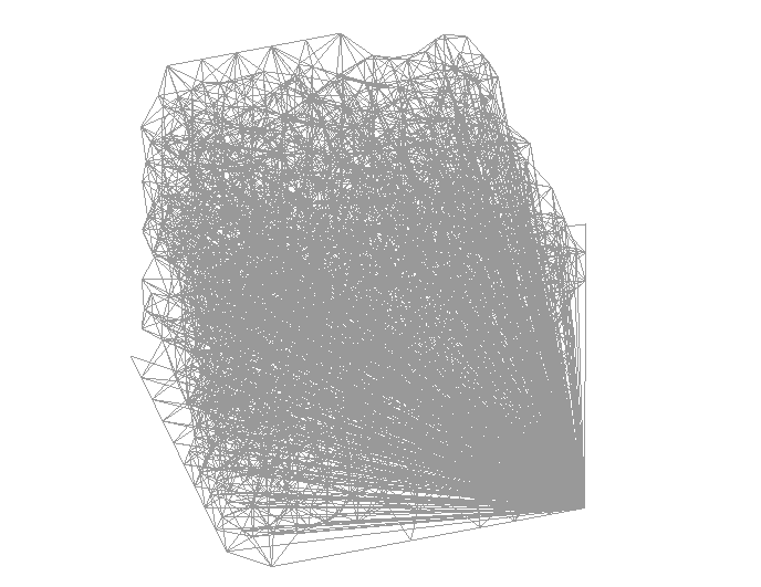
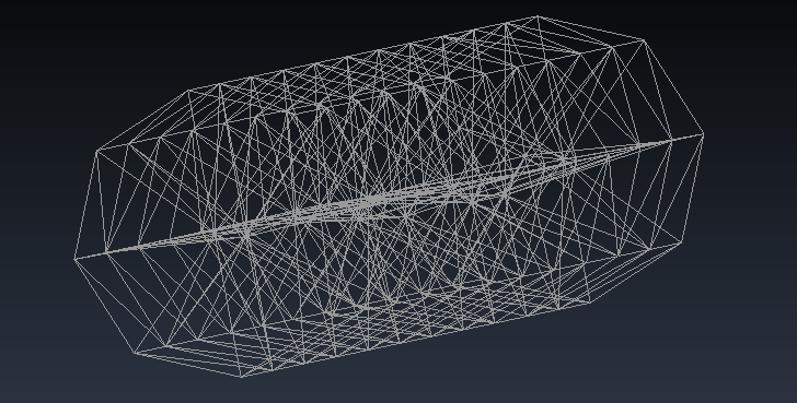
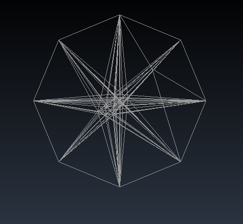
I also tried to install the 13.1.11d developer version, but the result after I used intersection tool, the result of 13.1.11d developer version is not as same as shown in the tutorial (the point on the circle). So I did not continued the drawing (see the attached images)
Now, I really dont know what is the problem.
So, I would like to ask that if the model is correct, but the mesh is wrong (partially), would it affect on the results after FEM analysis?
Sorry I don’t understand what is your last question (and seems that is not related to the initial question, please use different topics for different questions).
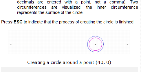
About your last pictures: The tool that create a circle has changed in latest GiD developer versions, now the starting point of the arc is on the upper point, in previous versions will be on the right of the circle.
The tutorials are related to a GiD version, doing the same with other versions could have some difference.
Which tutorial are you talking about?
Note: don’t try to follow tutorials like blind recipes, try to understand the concept of what is trying to do.
The tutorial I am talking about is the built-in Tutorials of GID.
As I m just a beginner, so now I want to know how to use the GID’s functions.
Thank you very much for your suggestion, I ll try to understand this program.
So, I would like to ask that if the model is correct, but the mesh is wrong (partially), would it affect on the results after FEM analysis?
It if is the related graphic card problem, (that show a wrong mesh just after meshing, but the mesh seems ok simply reopening the file)
then the mesh is really Ok in GiD, what seems that is corrupted is the copy of nodes coordinates that is stored in the graphic card memory.
in this case it won’t affect any FEM analysis, because the input file is written from the RAM data of GiD, that is not corrupted.
About following a tutorial,
If do you want to prevent possible small deviations from the behavior of the tutorial I recommend you to use a official GiD version (current last is 13.0.4).
Developer versions (current last is 13.1.11d) could have some (small) difference related to the tutorials (that were written for the official version)
In a month the last developer will become the next 14.0 official, and its tutorials will be updated to fit the current behavior
I have a problem about a tutorial exercise of the GiD-SAFIR software. The “tutorial for GID-SAFIR 3D Structural Analysis - exercise n°9 Hall 2 3D” (12/2011). I was able to do exercise n°8 correctly but as far as exercise n°9 is concerned, there is an error message when I generate the messages
"Condition ‘Beam-Load’ has flat ‘on body elements’ and maybe it needs flat ‘on face elements’ in the .cnd file in the problem type
Condition ‘Mass_on_Beam’ has flat ‘on body elements’ and maybe it needs flat ‘on face elements’ in the .cnd file in the problem type
Error when transfering condition ‘Beam-Load’ from geometry to mesh in line 10. It has notbeen transferredError when transfering condition ‘BEAM_Cross_section’ from geometry to mesh in line 10. It has not been trasnferredError when transfering condition ‘Mass_on_Beam’ from geometry to mesh in line 10. It has not been transferred. "
I do not understand the error, I don’t know how to solve it. I did the autorail many times to be sure to don’t forget anything, but it still doesn’t work. if you have any idea of the problem, thank you for your help.
The error/warning message mean than the condition named ‘Beam-Load’ was declared (defined in the .cnd of the problemtype) to be applied ‘over lines’ of geometry, and ‘over body element’ of mesh.
And the condition in applied to a geometric line that is not generating any ‘2-nodes line element’, and then the element to apply the condition doesn’t exists.
The line is not generating a ‘line-element’ because belong to a surface, and are generated quadrilaterals/triangles, and then by default GiD delete the lower-level line elements.
If the condition were defined ‘over face element’ then will be applied to some face of some quadrilateral/triangle with and edge over the line.
In this case is defined ‘over body element’ and then expect that the line element explicitly exists.
To force having the line-elements of a line that belong to a surface you must explictly say to do it, there are two ways:
assign the the desired line
Mesh->Mesh criteria->Mesh->Lines
and select the lines you want to force.
enable a global variable that say that ‘all lines’ must be forced to be meshed.
This is the option that is explained in this tutorial of SAFIR 2016 (I’ve just downloaded to have a look)
Do you have missed this point of the tutorial:
10.Generate Mesh
From the pull down menu select preferences , open the meshing tab and
select (beam) as “Mesh always by default†(in the bottom of the window)
The option could be in different place depending on your GiD version.
Now it is located in Utilities->Preferences…
Meshing->Other-Mesh always by default
select the icon of lines and press apply to accept the change.