This week, we received a question from our CIMNE BioMedical division (https://www.cimne.com/space/3240)
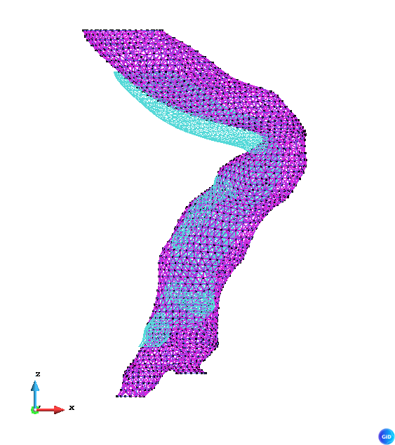
They import into GiD some STL files that define the surface of arterias, with holes for the inlet and outlets. For example:
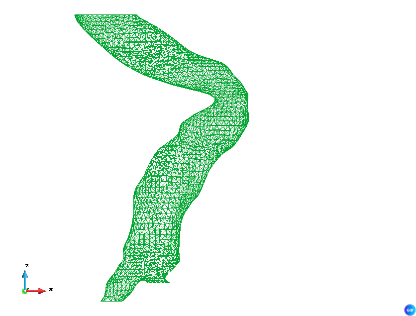
All the cuts are done using an XY cut plane so all the points in the cuts share the same Z coordinate.
They needed:
- To create geometry from the mesh.
- Assign the new surfaces to a group called “skin”.
- Create the covers:
- The one on the top, (greatest Z) will be the inlet.
- The rest will be the outlets.
- Each cover must be in an independent group, called “inlet”, “outlet_1”, … “outlet_n”.
- Once the surface is closed, it’s easy to create a volume and add it to a group called “body”.
They were doing all this in python outside GID but they were having troubles in the surface joint, that caused problems when generating the volume
So we prepared a tcl script that can be imported into GiD by just dropping the file over an opened GiD, or by using the GiD command line:
-np- source {path/to/this/script.tcl}
You will find this whole script at the end of this post.
Import the mesh
First of all, we import the STL using the GiD menú Files > Import > STL mesh
It can also be achieved in TCL using this command:
# Layer creation
GiD_Layers create Fluid
GiD_Layers edit to_use Fluid

# Mesh import
set stl_body "${model_directory}/body.stl"
GiD_Process MEscape Files STLRead $stl_body escape escape

# Layer -> Group
Groups::LayersToGroups Fluid
As you can see, we create a new layer, set to use, and import the stl file, so the mesh is imported into a new layer. This will make easier to create a group based on the layer. All the entitities in the layer will be now on a group called Fluid, that we can use in the problemtype to assign conditions.
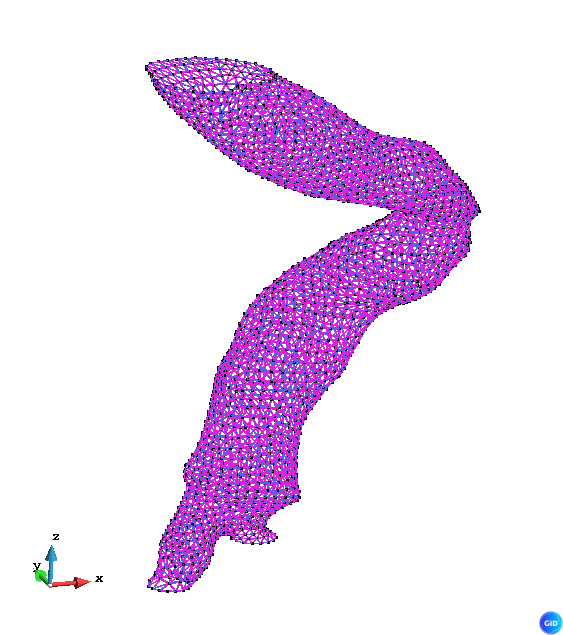
Convert from mesh to geometry
Once the group Fluid contains the mesh elements, we can convert it into geometry.
Using this script, we filter the elements, so in the selection we only select the entities in our group.
GiD_Process Mescape Geometry Edit ReConstruction OneSurfForEachElement Layer:Fluid escape
Creating the covers
The strategy will be the following:
- Detect the lines with higher entities 1 (meaning lines with number of connections 1)
- Group this lines based on the Z coordinate of theis points
- The group with higher Z will be the inlet, the others will be outlets
Higher entities 1
We can check it in GiD using the menú View > Higher entities > Lines
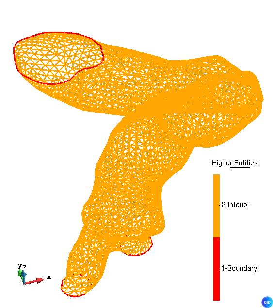
We are interested only on those lines with 1-Boundary.
To get those lines in our tcl script, we can use the following command:
set all_lines [GiD_Geometry list -higherentity 1 line]
Group by Z coordinate
We could do this in fewer lines, but it’s more didactical to do it like this. We are going to iterate over the lines, get the nodes, get the Z coordinate, do the mean, and add the line to an array, using the Z value as key.
array set groups {}
foreach l $all_lines {
    lassign [GiD_Geometry get line $l] types layer n1 n2
    set zlist {}

    lassign [GiD_Geometry get point $n1] layer x y z
    lappend zlist $z

    lassign [GiD_Geometry get point $n2] layer x y z
    lappend zlist $z

    set zmean [expr {([lindex $zlist 0] + [lindex $zlist 1]) / 2.0}]

    set key [format "%.6f" $zmean]
    lappend groups($key) $l
}
Create the covers
Once the array contains the lines, we can create them to generate the surfaces.
We are going to iterate over the keys, knowing that the higher will be the inlet, and using the lines to create the surfaces.
# Sort keys decreasing so the first will be the inlet
set zkeys [lsort -real -decreasing [array names groups]]

set idx 0
foreach z $zkeys {
    set lines $groups($z)
    if {[llength $lines] >= 3} {
        # Create surface
        set new_surface [GidUtils::CreateSurfaceFromBoundaryLines $lines]

        # assign name to group
        if {$idx == 0} {
            set name "Inlet"
        } else {
            set name "Outlet_[expr $idx -1]"
        }

        GiD_Groups create $name
        GiD_EntitiesGroups assign $name surfaces $new_surface

        incr idx
    }
}
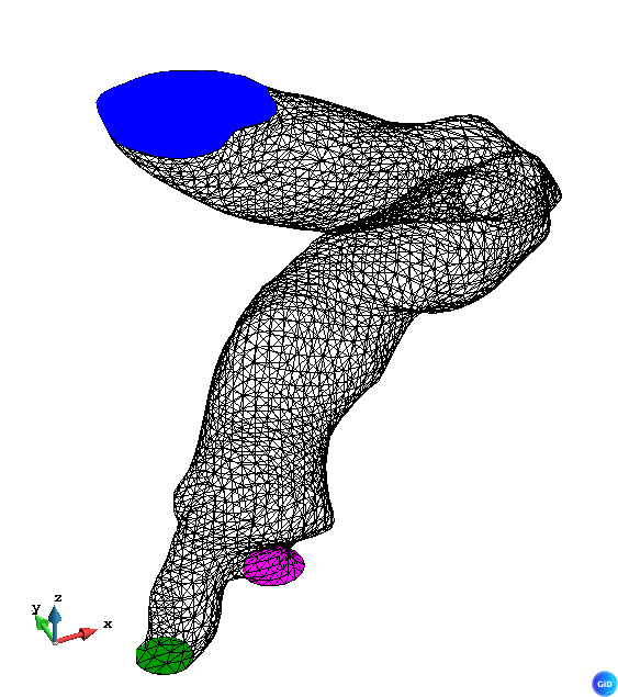
In our case, the following groups will be created, with the surfaces assigned
- Inlet (Blue)
- Outlet_0 (Pink)
- Outlet_1 (Green)
Generate the volume
Now we are going to rename the body group to skin, since it’s really the skin of our flow, and use the tool to generate the volume by contour, filtering the surfaces from our groups, and add it to a new group Fluid
# rename group
set lines [list ]
foreach group_name [list Skin Inlet Outlet_0 Outlet_1] {
    lappend lines {*}[GiD_EntitiesGroups get $group_name surfaces]
}
set volume [GidUtils::CreateVolumeFromBoundarySurfaces $lines]

GiD_Groups create Fluid
GiD_EntitiesGroups assign Fluid volumes $volume
The result looks like this:
As you can see, the volume is created.
Conclusion
Do you find this scripts interesting? In this case, this is part of an automated process and all this actions are executed in background, so no user actions are required.
The engineers at CIMNE BioMedical do have thousands of STL of real arteria with a lot of possible deformations, but this script will help them to increase the robustness of their process, and the simulations will require a bit less of human supervision in the geometrical part, allowing them to focus on the results of the analysis.
You can ask Dr. Soudah for further information
Code
You can find the script directly on our GitHub